
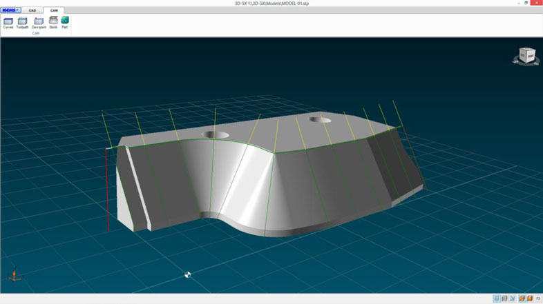
TAPER CONTROL
When cutting with low speed, the jet will erode more material from the bottom of the part than cutting with higher speeds. Since we are making speed compensations for corners etc. the measurement on the top/bottom of the part is different and the angle will not be straight.
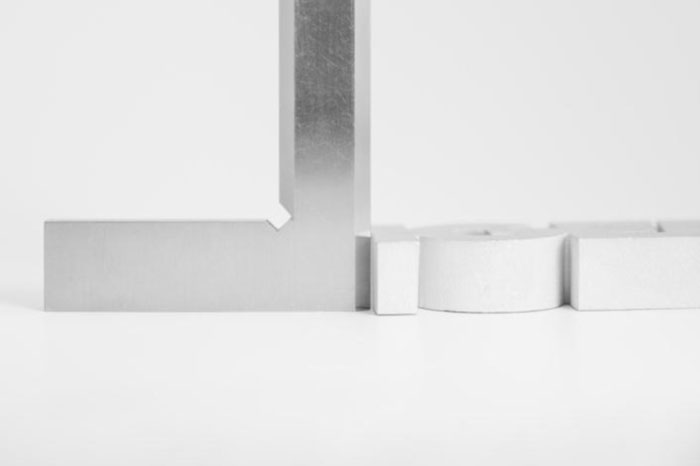
By activating the taper control, the jet will compensate for these errors and make straighter cuts.
DESIGN 3D PARTS FROM 2D
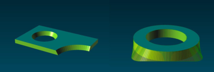
You can make standard 2D parts in IGEMS and add cutting angles afterwards. It’s perfect for fast programming with simple designs. You can also create 3D parts from a top and a bottom geometry. When using this method, you can create more complex 3D parts using IGEMS.
3D FILES
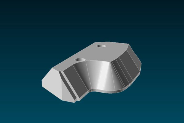
3D-5X can use STEP and IGES files containing surfaces and solids. It means that you can cut directly on models from your 3D system. (Inventor, SolidWorks, SolidEdge etc.) Just open the file in IGEMS and add a toolpath. 3D-5X is very easy to use compared to other 3D softwares, even on complex geometry.
Full 5 axis machining
3D-5X will supply you with full 5 axis information, meaning X, Y and Z linear positions and A, B and C information for the 5 axis kinematics.
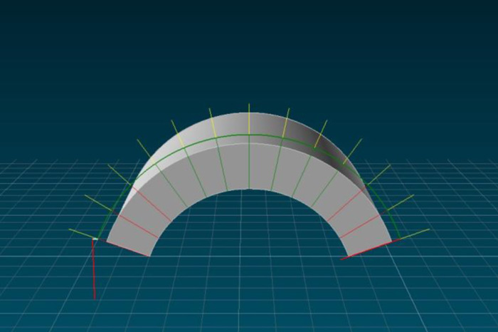
Cutting speed
The speed optimisation is very important for 5 axis cutting. It’s calculated from the actual thickness at every point, the geometry profile and the tilting direction. Piercing times are also calculated in a similar way. All the speeds are optimized from your pump pressure, orifice, mixing tube diameter and the amount of abrasive.
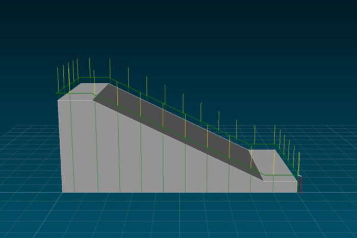
It’s also possible to control what portions of the model to cut. In this example, (A) is cut from the top of the contour to the cutting table. (B) is cut with just the length of the edge.
Nesting
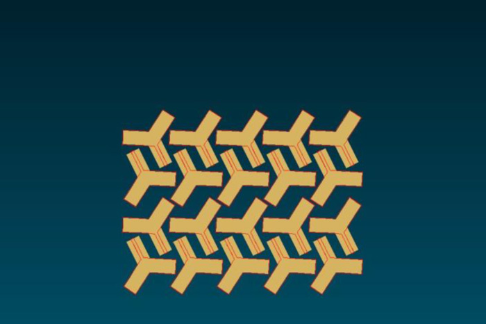
The 3D-5X parts can be nested just as any normal 2D parts. It’s calculated with the different cutting angles so the jet won’t damage other nested parts.
Full simulation
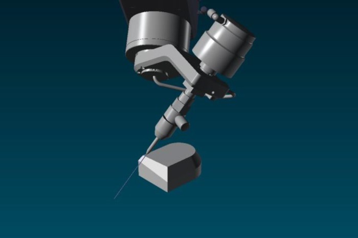
IGEMS can make full 3D simulation of the actual part and the 5 axis kinematic cutting head before you start cutting. It means that you can see what will happen before you cut your parts in the machine.
Features
• Add toolpaths from information in STEP or IGES files.
• Special analysis of the geometry to optimise for waterjet cutting.
• Part rotation to align the part correct to the machine.
• CAD commands to add help geometry in 3D, such as lines, arcs and circles.
• CAD commands to extend and project 3D objects.
• Automatic speed calculation depending on thickness and cutting parameters.
• Automatic speed ramping depending on geometry.
• Automatic piercing time calculation depending on thickness and cutting parameters.
• 5 axis cutting tool kerf calculation that can be visualised directly during the toolpath generation.
• Add bridges and tabs to fixate the part in the material.
• Nest 3D-5X parts.
• Full simulation of 3D-5X cutting.
• Support for all 5X kinematic heads on the market.
• Taper control on portions of the part with straight cut.
• Cutting vectors (tilt directions) can be adjusted manually to avoid collision between cutting head and work piece.
• Export 3D geometry to 2D.
• Import 2D geometry to 3D.
• Set zero point to any point on the model.
• Lead in/out and piercings can be placed in any directions and planes.
• STEP/IGES files will be embedded in the standard IGEMS DIG file.